
How Automatic Soap Dispensers Work: Sensor, Controller, Pump, Tubing, Reservoir, Dose and Power Architecture
Automatic soap dispensers by Fontana are designed for touch-free soap delivery in commercial restroom and wash-station applications. Depending on the model, the system may use a deck-mounted or wall-mounted dispenser body with concealed components located below the countertop or within an accessible service area. Commercial configurations can include a metal dispenser body, infrared sensor, electronic controller, soap pump, supply tubing, refillable reservoir, power source, and the associated sensor and power wiring.

How the Infrared Sensor Actually Works
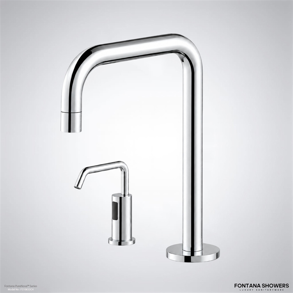

Fontana automatic soap dispensers that specify an active infrared sensor use optical infrared detection. The sensor incorporates an infrared emitter and receiver. The emitter projects infrared light into the intended hand-detection area beneath the dispenser outlet. When a user’s hand enters that area, some of the infrared light is reflected back toward the receiver. The resulting sensor signal is sent to the dispenser’s electronic controller, which determines whether a valid activation condition has been detected.
Infrared sensing should not be described as ultrasound or microwave sensing. Ultrasound, microwave, and infrared are different sensing technologies. An infrared soap dispenser does not become an ultrasonic or microwave device simply because it detects a hand without physical contact.
Sensor, Controller, Pump, Tubing, and Reservoir Architecture

Once the infrared sensor detects a hand, the signal is passed through the sensor cable to the electronic controller. The controller acts as the logic and switching component of the system. After confirming an activation, it supplies power to the soap-delivery mechanism for the programmed dispensing cycle.
Infrared Sensor
Detects the reflected infrared signal produced when a user’s hand enters the intended sensing field.
Electronic Controller
Processes the sensor signal and switches power to the dispensing mechanism for the programmed cycle.
Soap Pump
Moves soap from the reservoir toward the dispenser outlet after controller activation.
Supply Tubing
Provides the controlled soap-delivery path between the reservoir, pump and dispenser outlet.
Reservoir
Stores the soap supply within the accessible concealed service area.
Power System
Supplies electrical energy for sensing, electronic control and temporary pump operation.
Peristaltic Pump Operation
In Fontana commercial models equipped with a peristaltic pump, the pump moves soap without requiring the soap to pass through the pump’s mechanical drive components. Instead, the pump compresses flexible tubing in sequence, drawing soap from the reservoir and pushing it toward the dispenser outlet. The typical delivery path is:
Soap reservoir → pump inlet tubing → peristaltic pump → outlet tubing → dispenser spout → user’s hand.
The soap reservoir is normally installed below the countertop or inside the service cabinet. Tubing connects the reservoir to the pumping assembly and then continues toward the dispenser outlet. The sensor cable, controller, pump, power components, and reservoir remain accessible below the counter for inspection, refilling, adjustment, and maintenance.
How the Soap Dose Is Controlled
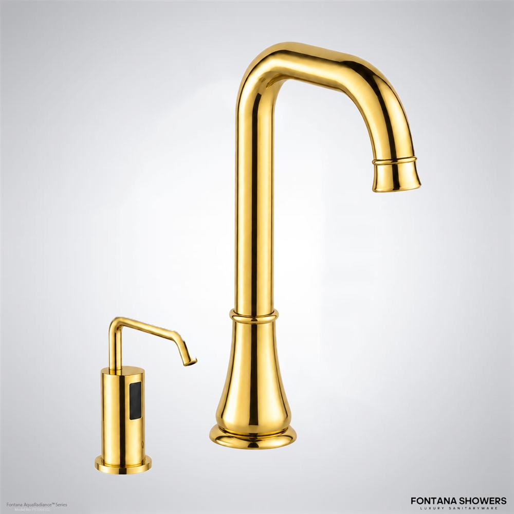
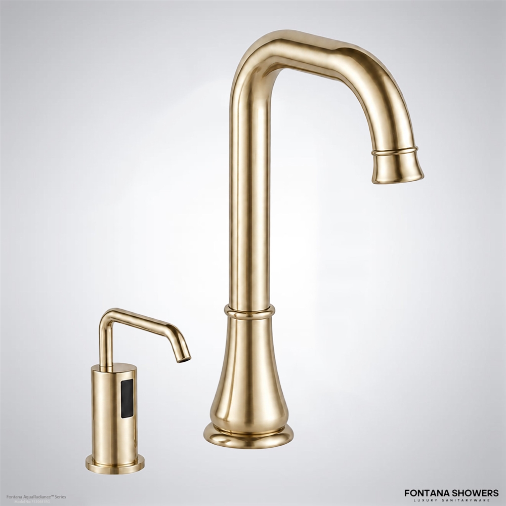
The dispenser does not simply run continuously while a hand remains beneath the sensor. After a valid infrared activation, the controller operates the pump for a defined dispensing cycle. The resulting dose per activation is determined by the pump configuration and the dispenser’s adjustable output setting. On models that provide adjustment, the amount can be changed to suit the soap formulation, facility requirements, and desired consumption rate.
Because Fontana dispenser models use different controllers, pumps, reservoirs, and adjustment ranges, a single dose value should not be presented as universal across the entire product line. Published Fontana specifications should be checked for the individual SKU before stating a specific milliliter-per-activation value.
Power Architecture

The electrical system powers three primary functions: infrared sensing, electronic control, and pump operation. Depending on the dispenser model, Fontana commercial systems may operate from batteries, an AC/DC power arrangement, or an optional AC adapter. During standby, power is required primarily for the sensing and control electronics. When a hand is detected, the controller temporarily energizes the pump to complete the dispensing cycle.
Functional Operating Sequence
The functional sequence can therefore be described as:
Power supply → infrared sensor detects hand → controller validates activation → controller energizes pump → pump draws soap from reservoir → soap travels through tubing → measured dose exits the spout → controller stops the pump and returns the system to standby.
Liquid Soap and Foam Systems Are Not the Same

Standard liquid-soap dispensers and foam-soap dispensers should also be described separately. A conventional liquid dispenser meters liquid soap through its pump and tubing directly to the outlet. A foam configuration may incorporate additional air-handling or liquid-and-air mixing components to produce foam before discharge. That foam-generation stage should only be described when it is documented for the specific dispenser model.
Accordingly, general statements that every Fontana automatic dispenser creates a vacuum to produce microbubbles should be avoided unless the particular SKU is specifically identified as a foam dispenser and its manufacturer documentation confirms that operating method.
Sensor Range Should Be Specified by Model

The activation distance is also model-specific rather than universally 3.35 inches. Commercial Fontana dispensers may use self-adjusting or adjustable infrared sensing, and some models provide sensor-range adjustment through an optional remote control. Countertop material, basin geometry, reflective surfaces, dispenser position, and installation conditions can also influence the appropriate sensing configuration.
For specification and installation purposes, the sensing distance, soap dose, reservoir capacity, pump type, power requirements, and adjustment method should therefore be taken from the technical documentation for the exact Fontana product being installed rather than generalized across all automatic soap dispensers.
Automatic Dispenser Specification Architecture
The principal components and values should be verified at individual product-SKU level before they are used for commercial specification or installation.
| System Element | Primary Function | Specification Consideration |
|---|---|---|
| Infrared Sensor | Detects hand presence through optical infrared reflection. | Detection range and adjustment method are model-specific. |
| Controller | Validates sensor input and controls the dispensing cycle. | Controller configuration varies by SKU. |
| Pump | Moves soap from reservoir toward dispenser outlet. | Verify whether the individual product specifies a peristaltic or other pump design. |
| Tubing | Provides the soap path between reservoir, pump and outlet. | Routing should remain accessible for inspection and service. |
| Reservoir | Stores the refillable soap supply. | Capacity and installation location vary by model. |
| Soap Dose | Controls the quantity discharged during each activation. | Use the exact product specification rather than a universal dose value. |
| Power | Supports sensor, controller and pump operation. | May include battery, AC/DC or optional adapter arrangements depending on model. |
Materials, Finishes, and Commercial Configuration


Fontana automatic soap dispensers are available in a variety of commercial configurations and decorative finishes, including chrome, brushed nickel, black, bronze, brushed gold, and polished gold options depending on the product. These finish choices allow the dispenser to coordinate with faucets and other restroom fixtures while the concealed sensor, controller, pump, tubing, reservoir, and power components perform the automatic dispensing functions below or behind the finished mounting surface.
Commercial Specification Summary
Sensing Technology
Infrared should be identified as optical infrared detection, not ultrasound or microwave sensing.
Activation Logic
The electronic controller validates the sensor signal before energizing the dispensing mechanism.
Soap Delivery
Soap moves from the reservoir through the pump and tubing toward the dispenser outlet.
Dose Control
Output is determined by the model’s pump, controller and available adjustment settings.
Electrical Supply
Power architecture can vary between battery, AC/DC and optional adapter configurations.
SKU Verification
Sensor range, reservoir capacity, dose, pump type and power requirements should be verified by product.
Most Common Inquiries
Digital Twins, Consumption Modeling & Predictive Maintenance
AEC guidance for digital-twin modeling, consumption forecasting, reservoir optimization, historical-data requirements and occupancy-based analytics for centralized commercial soap-distribution systems.
Could a digital twin accurately predict soap consumption and component degradation for an entire restroom?
Yes; digital twins can forecast consumption and degradation when calibrated with activation, occupancy, refill, maintenance, and component-condition data.
What variables would a useful digital twin need to monitor?
Monitor activations, dose volume, reservoir level, occupancy, pump current, pressure, temperature, faults, refill history, and maintenance events.
Could digital twins optimize reservoir size after actual occupancy patterns become known?
Yes; actual activation histories can refine reservoir sizing, service intervals, contingency volume, and zoning after occupancy patterns stabilize.
How much historical dispensing data is required before consumption predictions become reliable?
No fixed duration applies; reliability improves after data captures representative weekdays, weekends, seasonal peaks, closures, and special events.
Can restroom occupancy sensors predict soap consumption better than simple dispenser activation counts?
Usually, activation counts predict soap demand more directly; occupancy sensors improve forecasts when correlated with restroom use and non-users.


