
How to Specify a Commercial Touchless Bathroom Faucet
Commercial sensor-faucet selection should begin with the lavatory, plumbing conditions, electrical strategy and service requirements—not a generic list of touchless-faucet benefits. The correct fixture is the one whose geometry, sensor field, hydraulic requirements, mounting arrangement and control components coordinate with the complete restroom assembly.

Start With Coordination, Not Appearance
Finish and styling remain part of the architectural selection, but they should follow physical and technical coordination. A commercial touchless faucet functions as part of an assembly consisting of the basin, countertop, faucet body, sensor, valve, supply, electrical source and service zone.
Establish bowl dimensions, rim geometry, deck thickness and faucet-hole position.
Compare spout projection and outlet location with the intended basin landing zone.
Confirm sensor arrangement, valve architecture, pressure, flow and power source.
Coordinate under-deck equipment and future access before finalizing the specification.

Basin Geometry
A faucet should be coordinated with the actual basin rather than specified as an isolated component. Basin depth, bowl width, rear rim position, backsplash condition and mounting surface all influence fixture placement.
Bowl Envelope
Review the bowl’s front-to-back and side-to-side dimensions so the outlet and sensor operate over usable basin space rather than the rim or backsplash.
Deck Relationship
Confirm the faucet-hole location, deck thickness, mounting-hole requirement and available underside clearance for fastening hardware.
Backsplash Clearance
Check fixture-body clearance from vertical surfaces and confirm that cleaning, installation and sensor operation will not be obstructed.


Spout Reach and Water-Stream Landing
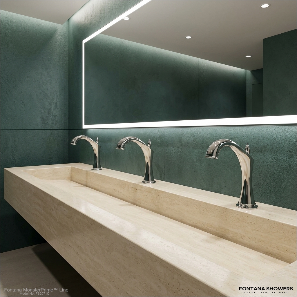
Spout reach is a coordination dimension. The relevant question is not whether a faucet is described as short, standard or extended reach, but where its outlet is positioned relative to the bowl.
Review the Horizontal Relationship
- Back edge of basin to faucet centerline
- Faucet centerline to outlet
- Outlet to intended water landing area
- Water landing area to drain location
- Clearance from the inside face of the basin rim
Review the Vertical Relationship
- Deck surface to outlet elevation
- Basin rim to outlet elevation
- Available handwashing clearance
- Relationship between stream trajectory and bowl depth
- Potential splash interaction with shallow basins

Read More: Spout-Reach Coordination Table
| Coordination Item | What to Verify | Primary Source |
|---|---|---|
| Spout projection | Horizontal outlet position relative to faucet centerline | SKU dimensional drawing |
| Outlet height | Vertical distance from mounting surface to outlet | SKU dimensional drawing |
| Basin landing zone | Expected stream location inside the bowl | Faucet + basin coordination drawing |
| Deck position | Mounting-hole location relative to bowl rim | Countertop / lavatory drawings |
Sensor Architecture
The sensor is a design component, not simply an on/off feature. Sensor location, detection direction, range adjustment and control architecture should be matched to the lavatory and project environment.
Sensor Location
Identify whether sensing is integrated into the faucet body, positioned near the spout, or arranged as part of another control configuration.
Detection Zone
Review the manufacturer’s intended activation envelope and confirm that the user’s hands enter the detection area naturally when positioned over the basin.
Reflective Conditions
Highly reflective basin finishes, unusual sink geometry or nearby surfaces should be reviewed where they could interact with the sensor field.


Flow Rate and Operating Pressure
Flow and pressure should be taken directly from the selected SKU documentation. Different commercial faucet configurations may use different outlets, aerators, control valves and supply arrangements.
Flow Data
Record the published flow rate for the exact model and outlet configuration.
- Published GPM and/or L/min
- Outlet or aerator configuration
- Applicable project water-use requirement
- Any available alternate flow configuration
Pressure Data
Confirm that project pressure conditions fall within the manufacturer’s operating range.
- Minimum operating pressure
- Maximum operating pressure
- Static versus available flowing pressure
- Pressure-loss implications of upstream components

Read More: Hydraulic Verification Fields
| Hydraulic Field | Enter Selected-SKU Value | Coordination Responsibility |
|---|---|---|
| Flow rate | Per current product/submittal data | Plumbing / sustainability |
| Operating pressure | Per current product/submittal data | Plumbing |
| Supply connection | Per current installation data | Plumbing |
| Temperature arrangement | Cold, premixed or mixed-water configuration per SKU/project | Plumbing / MEP |
Power and Control Strategy
Power architecture affects rough-in, maintenance planning and electrical coordination. Confirm the exact arrangement supplied with the faucet rather than assuming that every sensor fixture uses the same power source.
Battery
Where battery power is specified, identify battery type, quantity, enclosure location and the access path required for replacement.
AC / Transformer
Where mains-powered equipment is used, coordinate transformer location, electrical source, cable routing and accessibility with the electrical documents.
Hybrid / Alternate
If the selected SKU offers more than one power option, state the project-selected configuration clearly in the fixture schedule and submittal review.

Mounting and Rough-In Coordination
Mounting information affects countertops, lavatories, millwork, plumbing rough-in and the available service space below the fixture.
Deck-Mounted Faucet
- Mounting-hole requirement
- Maximum permitted deck thickness
- Fastener and shank clearance
- Supply and control component location
Wall-Mounted Faucet
- Finished-wall projection
- Valve/body rough-in depth
- Relationship to backsplash and basin
- Access to concealed components
Under-Deck Components
- Control box
- Solenoid valve
- Battery enclosure or power module
- Flexible hoses and isolation components


Service Access and Maintainability
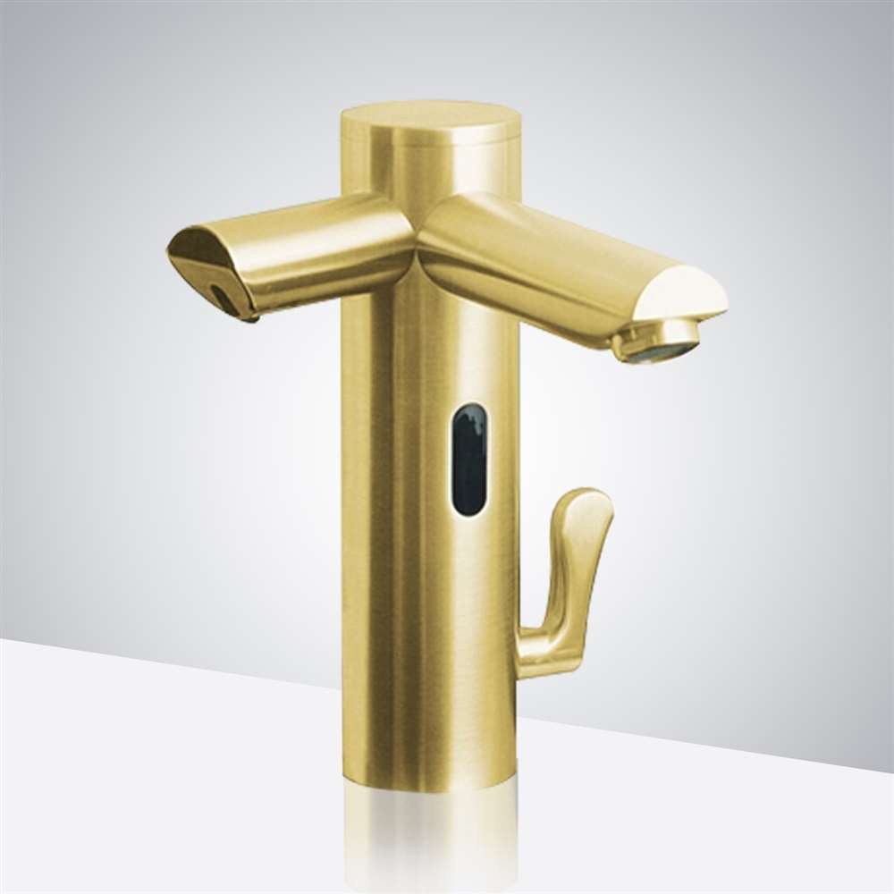
A fixture may fit the countertop but still be difficult to maintain. The specification should therefore evaluate the service zone around electronic, hydraulic and replaceable components.
Read More: Service-Access Checklist
BIM, Drawings and Submittal Coordination
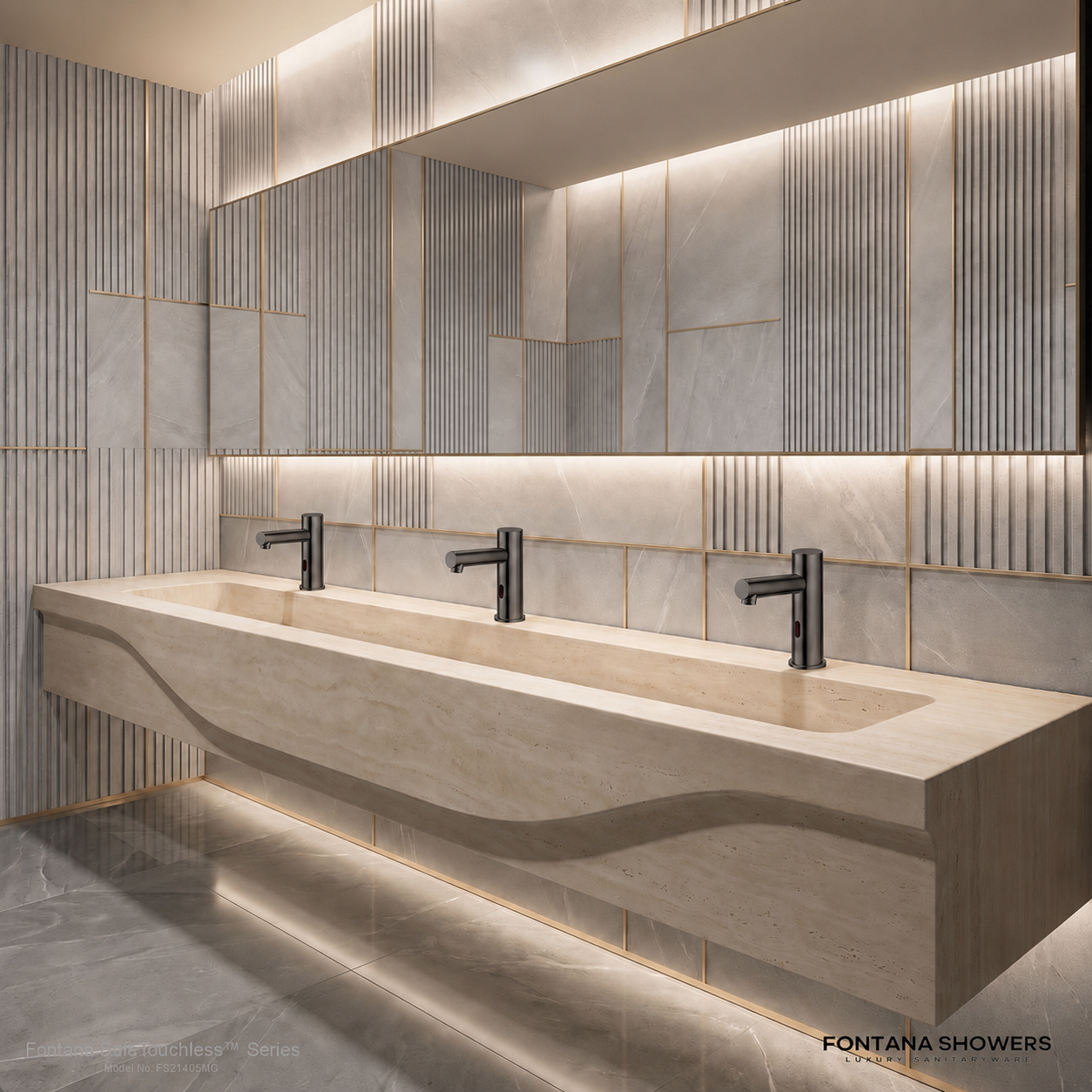
BIM should support dimensional coordination rather than serve only as a visual placeholder. The design team should verify that the modeled fixture corresponds to the selected product and that critical dimensions agree with current technical documentation.
Architectural Model
Coordinate fixture position, basin relationship, countertop penetration, visual clearance and accessibility requirements.
Plumbing Model
Coordinate water supply, valve/control components, connection sizes, isolation and serviceable under-deck equipment.
Electrical Model
Where applicable, coordinate power supply, transformer location, receptacle or connection requirements and cable routing.
Read More: BIM and Submittal Requirements
| Submittal Item | Required Coordination |
|---|---|
| Product data | Exact model number, finish, flow and power configuration |
| Dimensional drawing | Height, projection, mounting dimensions and component envelope |
| Installation instructions | Rough-in, supply, wiring and mounting sequence |
| BIM/CAD file | Geometry aligned with the specified SKU |
| Fixture schedule | Model designation consistent across architectural, plumbing and procurement documents |
Commercial Faucet Selection Matrix
Use the following fields when comparing candidate products. Values should be populated from current SKU-level manufacturer documentation rather than generalized category descriptions.

Read More: Full Commercial Faucet Selection Matrix
| Selection Field | SKU 1 | SKU 2 | SKU 3 |
|---|---|---|---|
| Mounting type | Verify | Verify | Verify |
| Overall height | Verify | Verify | Verify |
| Spout reach / projection | Verify | Verify | Verify |
| Outlet height | Verify | Verify | Verify |
| Sensor type / location | Verify | Verify | Verify |
| Sensor range / adjustment | Verify | Verify | Verify |
| Flow rate | Verify | Verify | Verify |
| Operating pressure | Verify | Verify | Verify |
| Supply connection | Verify | Verify | Verify |
| Power source | Verify | Verify | Verify |
| Control / solenoid location | Verify | Verify | Verify |
| Service-access requirement | Verify | Verify | Verify |
| BIM / CAD availability | Verify | Verify | Verify |
Pre-Specification Checklist
Read More: Complete Pre-Specification Checklist
Commercial Touchless Faucet Resources
Continue product research by mounting type, application and commercial sensor-faucet configuration.

Specify the System, Not Just the Faucet
Commercial touchless faucet selection is strongest when basin geometry, spout position, sensor field, hydraulic conditions, power, mounting and maintenance access are resolved together. Final selections should be based on current SKU-level technical documentation and coordinated across architectural, plumbing, electrical, BIM and procurement documents.


